|
QUICK RACING PRODUCTS
|
|
GTM Front Sway Bar Kit Install Tips |
|
|
||||||||||||||||||||
 |
|||||||||
 |
|||||||||
|
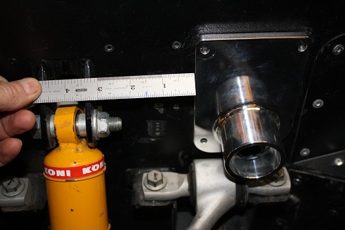
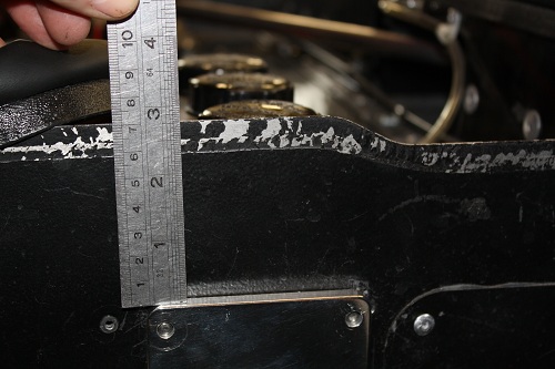
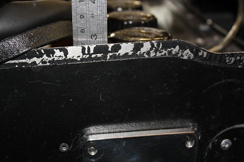
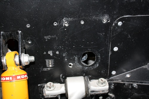
Remove bulb seal from side panel. Hold the mount so that it is level with the top of the upper frame rail & lines up with the mark drawn in the first step. Easy way is to measure from the top of the upper frame rail to the top of side panel. Transfer the measurement to the outside of panel. Make sure that the top of the mount is level with the top of the frame member. |
|||||||||
 |
|||||||||
 |
|||||||||
|
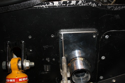
Once you have the mount in the correct position, transfer mounting bolt holes, & hole for bar to pass through onto side panel. Drill pilot holes for mounting bolts through side panel & frame members. Holes should be in center of frame tubes. Then drill 1/4 holes in top frame & 5/16 in diagonal frame member. Then hole saw opening for sway bar with 1 1/8 - 1 1/4 hole saw, being careful not to cut into firewall on right side. |
 |
|||||||
 |
|||||||
 |
|||||||
 |
|||||||
|
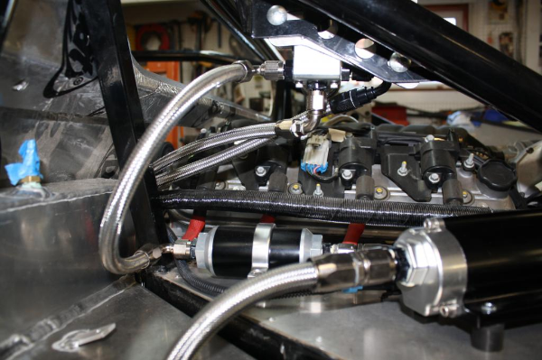
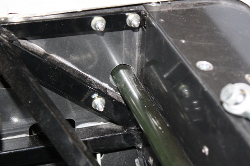
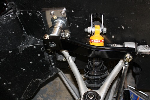
Make sure to clearance any brake lines, wiring harness, or any other components that may obstruct the mounting of the sway bar as it passes through the chassis. Once all holes are drilled, slide bar though chassis. Install nylon bushings into mounts, & slide mounts over bar. Loosely install mounting bolts through mounts & chassis. Position bar centered between mounts & lightly snug bolts. No lubrication is needed on bar/bushings. Slide arms onto bar, with the bar properly centered, a small amount of the bar will stick outside of each arm. Make sure that the arms are level side to side, splines on sway bar are timed evenly side to side. Once you have the arms mounted evenly/properly, tighten the bolts on the mounts. Make sure that the arms are flush against the bushings, install & tighten the bolts that clamp the arms to the bar. There will be tension/drag on the bar once the mounting bolts are tight. |
 |
|||
 |
|||
|
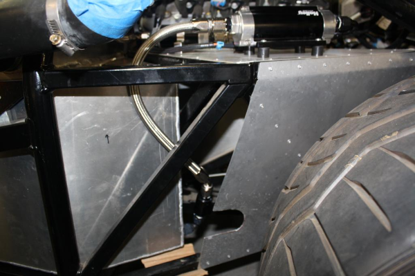
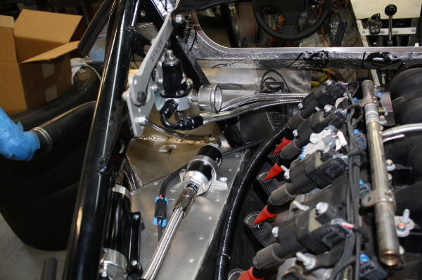
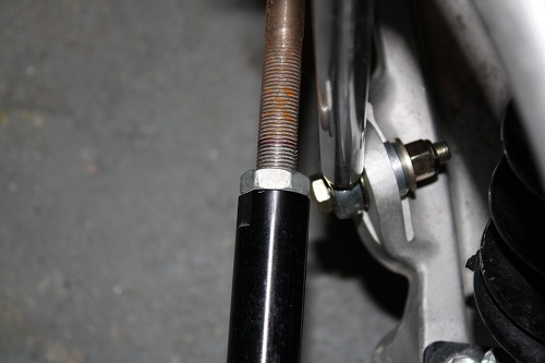
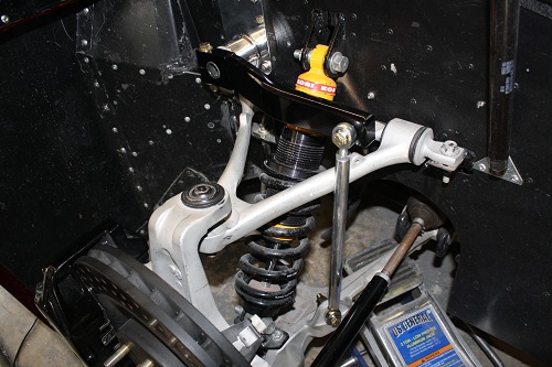
With the car on a level surface, with the proper ground clearance, install the aluminum links to the arms & to the lower control arms. Make sure that the heim joints are sticking out of the link equally on each end, they should have just a couple threads of the heim showing. On the arm end, make sure that you have the AN washer, & full washer against the arm, providing clearance for the heim joint. On the control arm, place the AN, & full washer between the heim joint, & the control arm mount - with the adapter bushing on the back side - this give clearance on the steering tie rod at full lock. Tighten the lower link bolts, & 1 of the upper bolts leaving 1 side loose. Making SURE that the chassis is level, with no bind or load, adjust the links by turning them. The heim joints are right/left so adjusting is easy. The bar is adjusted properly when the 1 upper mounting bolt that you left loose slides into the arm easily, with no binding. Then tighten the mounting bolt & tighten the jam nuts on the heim joints. Make sure all bolts are tight. turn the steering lock to lock & make sure there are no clearance problems.
Any questions, dont hesitate to contact us. |
|
Fuel System Installation Tips |
|
|
||||||||||||||||||||||||||||||||||||||||||||||||||||||||||||||||||||||||||||||||||||||||||||||||||||||||||||||||||||||||||||||||||||||||||||||||||||||||||||||||||||||||||||||||||||||||||||||||||||||||||||||||
| [Home] [New Products] [Contact Us] [Place Order] [Product Catalog] [Featured Service] [Instalation Tips] [Links] [Racing] [Media] [News] |